Purpose of the component
The purpose of sealing elements is to prevent leaking of gases. As it can be seen from the explosion view there are three different types of sealing elements inside the Open fuel cell.
The smallest sealings are located between the anode end plate and the anode flow field where the inlet and outlet of the hydrogen are sealed. The next bigger sealings are located between the anode flow field and the 6 mm SMC tube connectors. In both cases O-ring sealings could be used, however these O-ring sealing are not that easily available in general hardware stores.
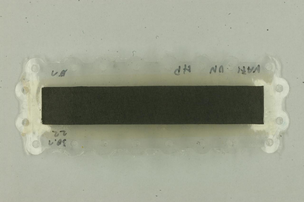
The most obvious flat sealing is located directly on both sides of the MEA. The anode compartment has to be sealed against the surrounding air to prevent hydrogen leakage. On the cathode side there is also a flat sealing element, but why. As it can be seen from the explosion view, the rims of the flat sealings will end up just opposite of each other. This is necessary to assure a homogeneous and flexible compactation of the interface between the sealing and the anode.
This sealing element consist of a small rim with a height and width of about 0.2 mm and 2 mm respectively. Due to the nature of this very flexible design the sealing element can level out any bump, crinkle, or what ever may occur on the surface of the MEA to assure a gas tight sealing. A further part is the big base which also has a height of about 0.2 mm. As with all big components of this cell, this base also incorporates holes through which the screws, which themselves act as both, as tight rods and dowel pins, can pass through.
Within the fuel cell production on an industrial scale this type of sealing may be applied directly onto the flow fields by a dispensing process using an according silicone component. Just imagine using your construction syringe, just on a smaller scale. However this approach is not really applicable if single part should be fitted with a sealing. This is especially true since a two component silicone is generally used for that applications, which has a limited shelf live after mixing the components together. A further option would be cutting the whole sealing out of big sheets of silicone rubber. However that would mean lots of waste. Furthermore we couldn’t find silicone sheets with an overall thickness of about 0.4 mm. Also the 3D-structure of the flat sealing including the base plate and the small rim can’t be cut out of that sheet material.
Here we can make use of the advantages of the FDM-3D-printing process regarding the flexible design of the components and the the required filaments can easily be stored.
What material is used
One of the most flexible materials available for the FDM-3D-printing is the „Filaflex 70A“ from the manufacturer „Recreus“. At the time we started with the development of the open fuel cell this material was, at least regarding to the information published by Recreus, the softest material available for 3D-printing. The „70A“ refers to the shore hardness of the material itself. With such a flexible material one can imagine, that a filament with a diameter of 1.75 mm made from such a flexible material is very flexible. To get an idea of how flexible the filament is take one of the licorice snail you might just enjoy and unroll them – and now try to ram the licorice filament down a clogged tube. You already have an idea what types of problems may occur?
How to produce it
As already mentioned, the very soft nature of the material renders it very difficult to be processed. Within the extruder of a FDM-3D-printer, although the nozzle is heated to temperatures above the softening point of the thermoplast, some kind of force has to be applied to the filament in order to push the soft elastomer through the orifice. Now imagine that there is a long way between the drive gear and the nozzle as it is the case with the bowden extruder systems quite often used in low cost printers. The long elastomer filament between the drive gear and the nozzle acts as a giant spring which limits the precision with witch the amount of extruded polymer can be controlled. Therefore it is highly advisable to use direct extruder to print this type of filaments. In our case the Prusa I3 MK3S printer is equipped with such a direct extruder. For the Prusa printer we made good experience with the presets for the Prusa Slicer provided by Recreus: https://recreus.com/de/content/24-druckparameter
To allow for the required flexibility of the layer height of the 3D-printed sealings, the height of the single print layer was set to 0,05 mm.
Upon automatic loading of the filament, the Prusa Printer applies very high feed rates to initially load the filament into the extruder. This bears a high risk, that the filament will be squeezed through the small gap between the drive gear and the entrance into the hotend of the extruder. If this happens you will have lots of fun fiddling the filament out of void spaces of the extruder. To prevent this from happening, go to the „SETTING“ menu of the printer and turn off the „Filament sensor“. This also disables the auto load function. In this case it is necessary to really load the filament down into the extruder hotend by hand. It is also advisable to reduce the pressure of the idler of the drive gear assembly.
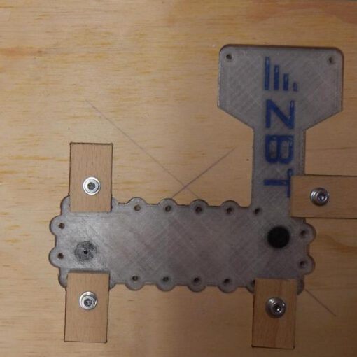
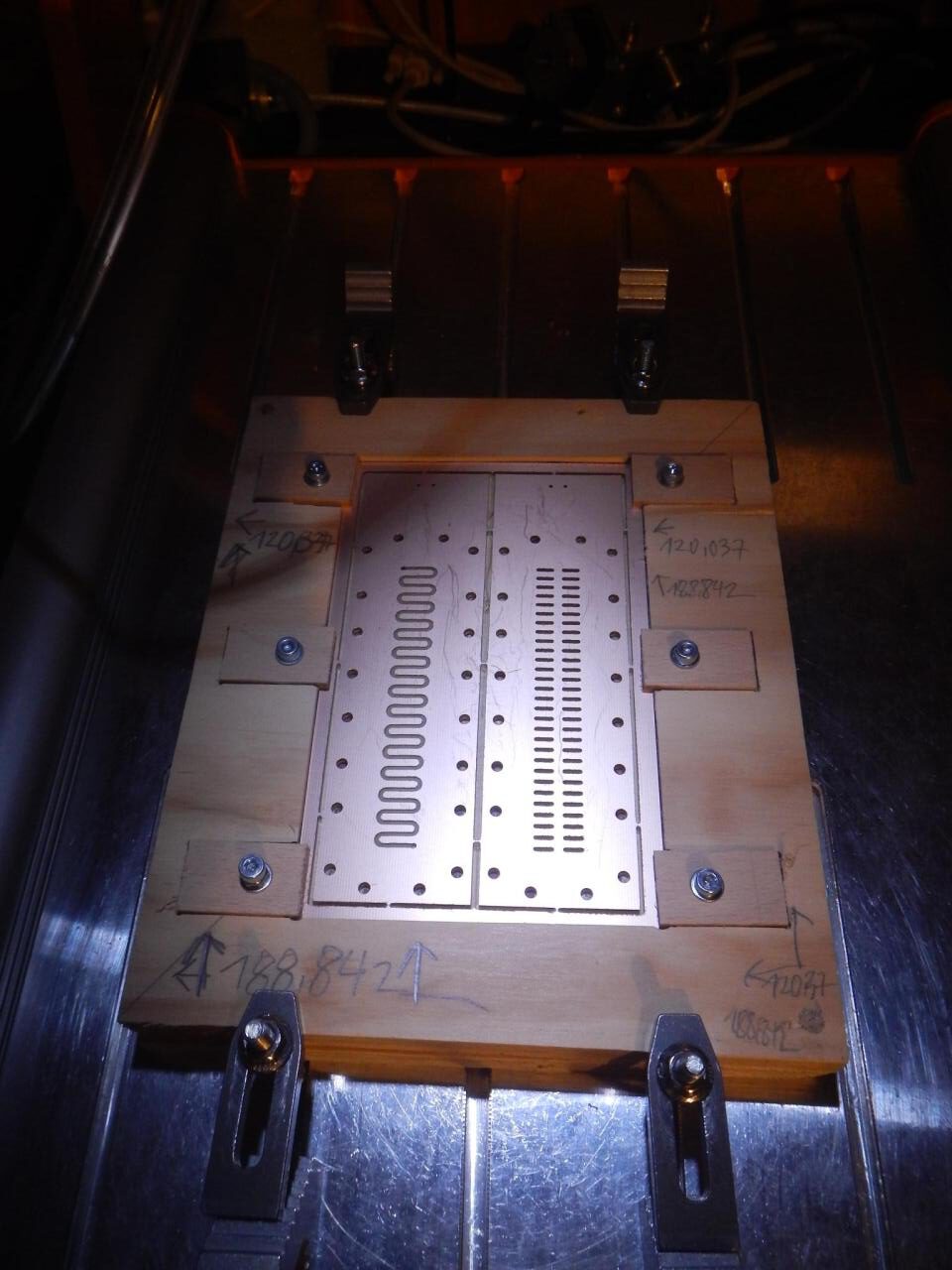
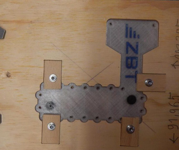
Printing with this flexible filaments also requires some pre treatment of the print bed itself. If this filament, especially while printing the thin flat sealings is directly printed onto the print bed it is nearly impossible to get the part off the bed in one piece. One of the easiest solutions consist of covering the complete bed with a thin layer of water soluble wood glue. After the printing process is completed just immerse the print bed into water for some hours. Afterwards it is possible to peel the flat sealing off the print bed. To get rid off the last glue residues from the sealings, they have to be carefully washed afterwards.
While processing this flexible filaments it has to be kept in mind, that the Filaflex material is hygroscopic. That means that it will take up water is stored under moist conditions. In order to allow for a smooth print it is advisable to dry the filament using e.g. a filament dryer prior to each print.

