The Membrane Electrode Assembly (MEA) is the central component of every PEMFC and has to fulfill a variety of different requirements. As a mechanical barrier it has to prevent the hydrogen and air/oxygen on the anode and cathode side respectively from mixing with each other and thereby generating an explosive atmosphere. To generate the electrical power catalyst layers are located at the interface of the membrane and the Gas Diffusion Electrode (GDE) on the anode and cathode side. Here the hydrogen is split into the electrons and protons on the anode side, while on the cathode side the oxygen reacts with these protons and the electrons arriving to water. How does the protons come from the anode to the cathode side? Well they will diffuse through the (humidified) membrane, while the electrons flow as an electrical outside e.g. through a current load, electrical engine, smart phone charger, … and can therefor be used for a variety of really useful applications. The next layers with a double function are the Gas Diffusion Layers (GDL) as a part of the GDE on the anode and cathode side as well. From a physical point of view the purpose of the GDL is to ensure a good distribution of hydrogen and air / oxygen on the anode and cathode side respectively. From an electrical point of view this layer also has to allow for a good electrical conductivity to get the electrical current to and from the catalyst layers to the flow field plates.
As you can see, the MEA fulfills a whole bunch of purposes inside a MEA and is in fact quite a complex component, although it just looks like a flat piece of something from the outside. In fact the purposes of all the other parts used to assemble an operational fuel cell are just to keep the MEA under good conditions and pumping. The MEA can therefore be referred as the heart of the fuel cell.
What material is used?
In order to produce a MEA the following items are needed:
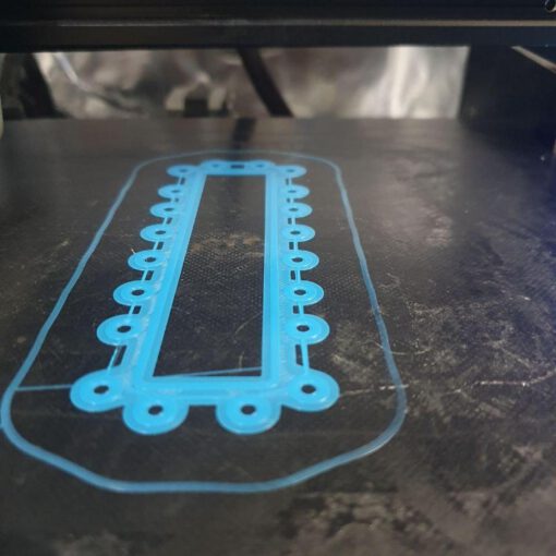
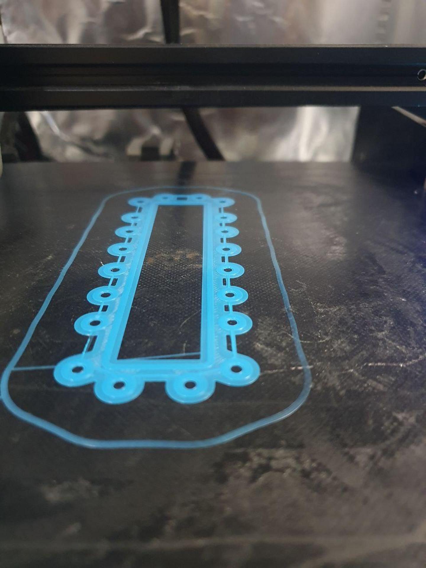
the edge reinforcements: This part is already described in its own chapter. We assume, that you have just cut them out of a sheet of laminating film using a drag knife
the membrane itself: The proton conducting membranes used in PEM fuel cell mostly consist of a polymer that belongs to the class of „Per-Fluoro-Sulfonic-Acid“ (PFSA). In the case of the MEA used for the OpenFuelCell project we use a 20 µm thick membrane which is known under the name „Nafion HP“ (The Chemours Company). Please keep in mind: Since that membrane is very thin and therefore quite sensitive, it is covered with protective films on both sides.
Gas Diffusion electrodes: In the case of the Open Fuel Cell we used Gas Diffusion Electrodes (GDE) that where produced in the ZBT.
How to make it?
Regarding the required manual work the MEA is definitely one of the more complicated component of the fuel cell.
Edge reinforced membrane
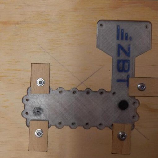
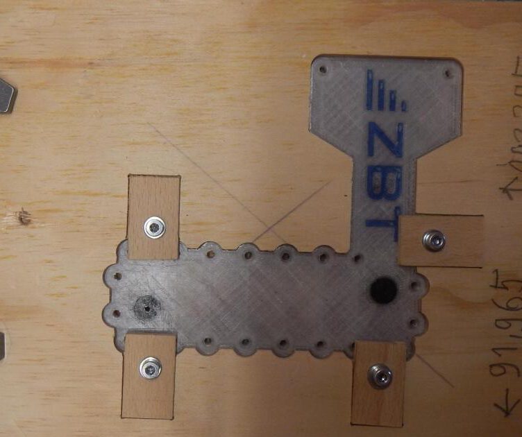
The first step is to assemble the edge reinforced membrane. You remember the ironing board described as one of the essential tools to build your own fuel cell? Take that board and place the first edge reinforcement with the glue layer facing upwards on top of it. Now fixate the edge reinforcement with the dowel pins on the ironing board. Next comes the PFSA membrane.
Keep in mind, that the membrane is covered with protective films on both sides for shipping. It is a little tricky, but you have to remove both protective films BEFORE assembling the MEA. Otherwise the fuel cell will not work at all. Should you have forgotten to remove that film – do not worry! You wouldn’t be the first one.
Place the piece of membrane in the middle of the ironing board on top of the first edge reinforcement. The membrane will be positioned by the dowel pins on all side.
Now place the second edge reinforcement on top of the membrane and the first, lowest edge reinforcement. The dowel pins have to go through the holes in the reinforcement.
In order to assemble the edge reinforced membrane remove heat up your iron to about 100°C and remove one of the dowel pins. Now place the iron in the gap of the missing pin and press the whole assembly together for a few seconds. After inserting the pin again, remove the next one and repeat the process. Continue to do so until all parts of the assembly are glued together. Of cause you may also remove several pins at the same time to allow for a bigger area to place the iron at once. It you have a steady hand you may do so. However keep in mind that the laminating film sourced from the office supply are covered with a simple melt glue that can be remelted over and over again. So even if the edge reinforced membrane is perfectly aligned at some first spots, everything can be ruined if all pins are removed, the iron is slammed onto the assembly and moved side wards a little bit.
If you are unsure at your first attempts it might be a good idea to practice that assembly step using just the edge reinforcements and a piece of paper as a model membrane. Both are chap – in contrast to the membrane.
MEA assembly
Once the edged reinforced membrane is assembled we can start the final assembly of the MEA itself.
Place the first GDE with the really black side facing up on a sufficient heat proof surface. Place the edge reinforced membrane on top of the GDE. Make sure that the GDE is is located in the area of the membrane itself and does not overlap with the edge reinforcement. The second GDE is placed on the top side of the edge reinforced membrane. This pile is hot pressed for several minutes at temperatures of about 150°C. Here in our lab we used a commercially hot press for that process.
During the development of the first MEA for the Open Fuel Cell we also performed that step using the handheld iron. We are not sure at the moment, if the high performance MEAs can be produced that way. Maybe you can figure out a way how the MEA can be produced using a conventional iron or the handheld hot press instead of using this industrial scale one. The challenge of that task will be not to rip up the alignment of the single parts of the edged reinforced assembly.
