The main purpose of the end plates is to assure an evenly distribution of the compaction force over the whole area of the fuel cell.
Table of Contents
Anode End Plate
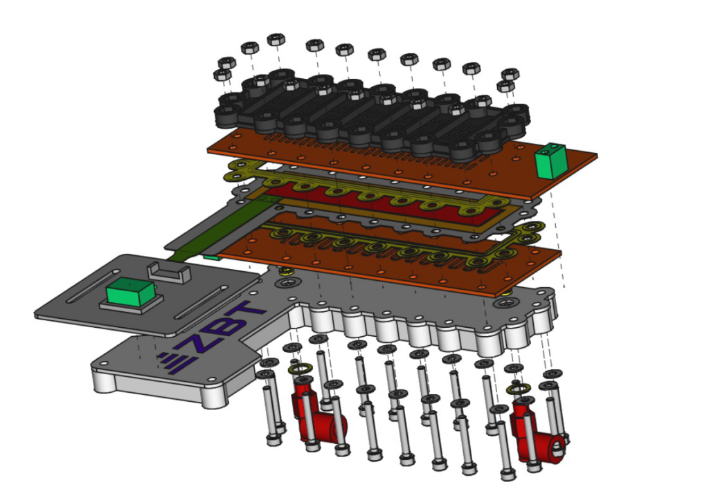
In the explosion view you can see that this anode plate (white with ZBT logo) acts as a guide for the screws with which the stack is held together. Since the screws also function as guide rods to align all internal components of the open fuel cell like flow field plates, sealings and the MEA, the anode end plate in combination with the cathode plate also acts as an template.
The red connectors for the hydrogen supply, inlet and outlet, are also attached to these components. That, of cause also means that the anode end plate has to contain gas tight channels to the flow field (brown) for the hydrogen gas.
Cathode End Plate
In the explosion view this component is located at the very top of the Open Fuel Cell, on top of the cathode flow field plate.
For the open cathode design of the Open Fuel Cell vents for the air to access the cathode of the PEMFC as well as to get rid of the product water have to be located inside the end plate. As it can be concluded from the explosion view the vents in the end plate end up just on top of the vents of the cathode flow field plate once the cell is assembled. A further functionality of the end plate it to keep the screws which are used to compress the PEMFC itself and also double as guide pins is place. In addition to that, to facilitate the assembly of the cell itself, this plate also has pockets to accommodate the M3 nuts. What is the great benefit of that? You do not need any spanner for the cell assembly.
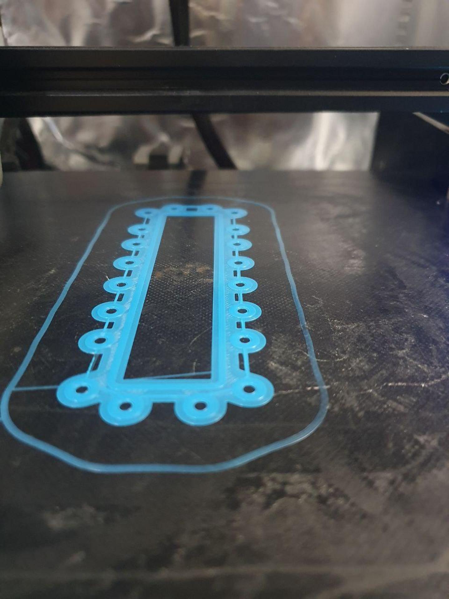
SLA Printing and Threads
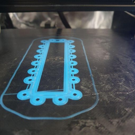
Stereolithography (Wikipedia) 3D printing is one of the two ways we produce end plates. We are still in the test phase of the SLA printing process. But the first results look promising.
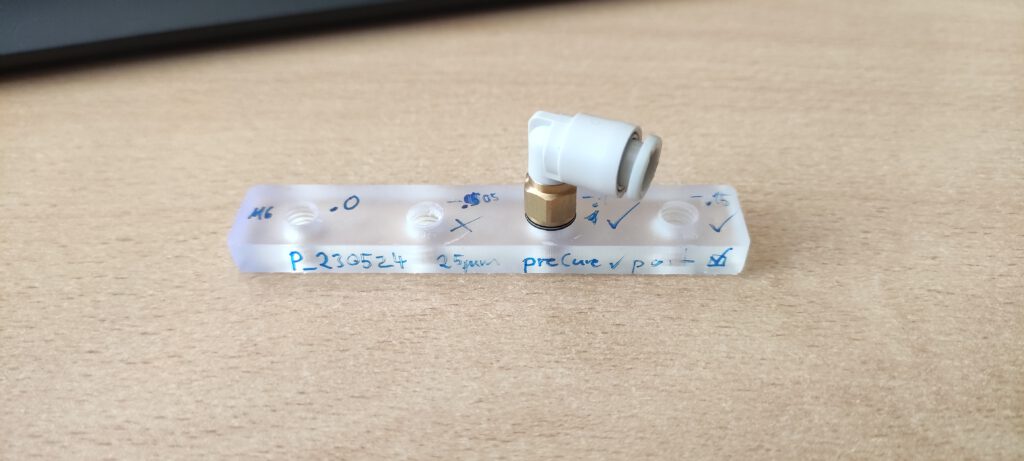
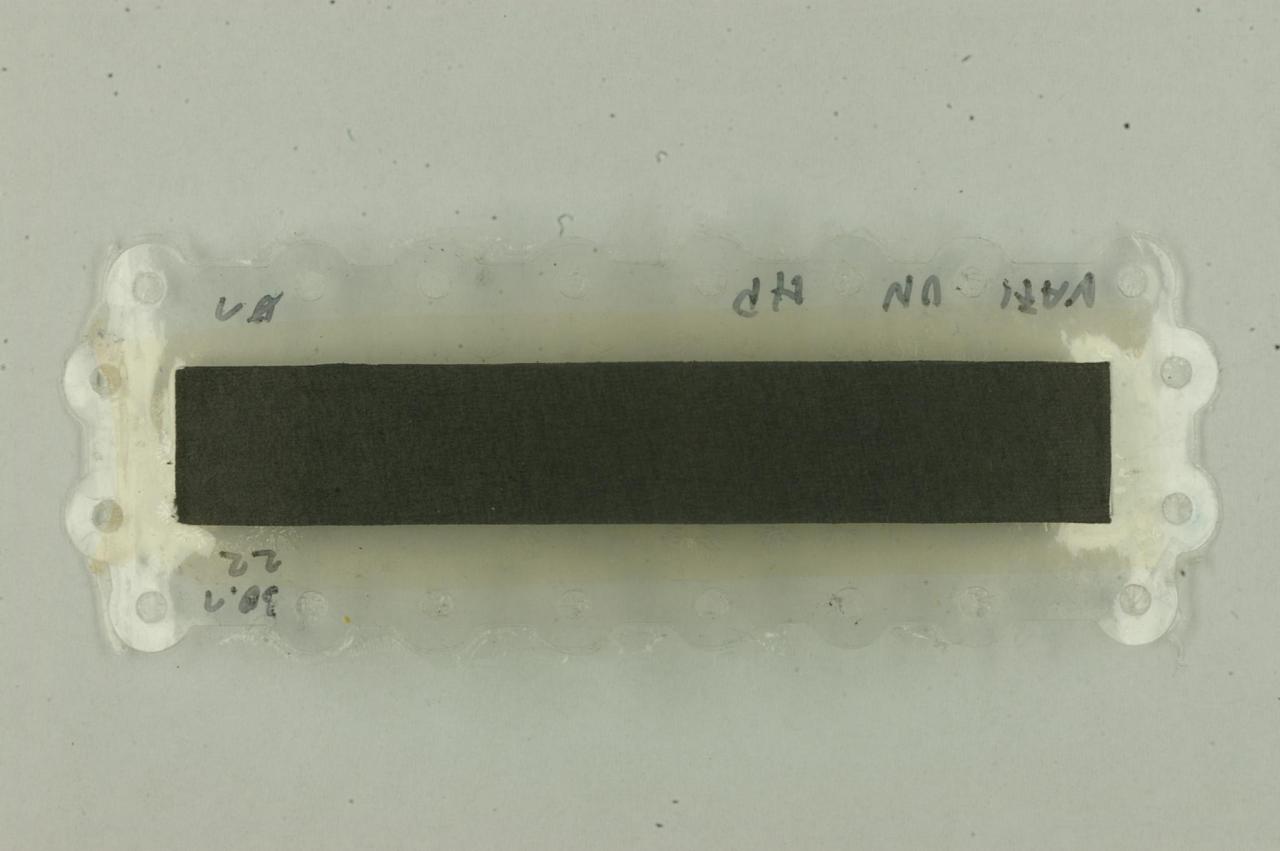
One disadvantage of SLA printing is that there is always an extra layer of overcured resin on the surfaces. For example, if you want a cylindrical hole with a diameter of 6 mm in a CAD design, the hole could be 5.8 mm after printing.
If you then would like to use a thread tap to make a M6 threaded whole, we observed cracking of the quite brittle material. To overcome this issue and to have an instantly working M6 thread after printing we used an offset function which most CAD systems offer. To avoid printing a lot of end plates with different offsets we made a calibration board (see Download Section) for M6 inner threads and we tested a range from .0 mm up till -.15 mm of offset at the threaded surface. It turned out at an offset of -.1 mm our Formlabs printer produces a smooth thread.

