This post will help you understand why you’d need flow fields and how to make them yourself from off-the-shelf printed circuit boards (PCBs).
Table of Contents
Why PCBs? Current collector and gas distribution
In a PEMFC, the flow field plates generally fulfil two different purposes. One is to conduct the current generated at the MEA (membrane electrode assembly) to the next cell or to the power outlet of the cell or stack. The second purpose is to distribute the gases, hydrogen on the anode side and air or oxygen on the cathode side, evenly across the MEA. These plates must therefore be made of electrically highly conductive material and must be produced with some form of flow field.
With the passive open cathode design and the comparatively low current density for which our open fuel cell is designed, a simplified layout can be used. While the anode flow field has a single meandering gas channel, the cathode flow field has only air vents. The second simplification is in the electrical conductivity. Due to the expected lower currents, it is not necessary to make the whole plate of conductive material, but to use only a thin conductive layer.
What material is used?
In large commercial PEMFCs, these flow field plates are made either from graphite/graphite composites or from formed sheet metal. However, forming or even milling solid metal is a little out of reach for low cost hobby applications. Milling graphite composite can be quite messy and the base material is not easy to come by. For our cell, we are not aiming for the high current densities of up to 2 A/cm² of commercial active cells. We want a low cost, easy to manufacture, functional and very robust design. So the material of choice is epoxy-based (FR4) circuit boards with 35 µm copper cladding on one side, available from almost any electronics supplier. As you can imagine, copper is prone to corrosion, or verdigris. This has a detrimental effect on the performance of the fuel cell. The direct effect is that the electrical conductivity of the verdigris is quite poor compared to that of clean copper and therefore significant electrical power losses will occur. The indirect effect is that the copper ions released during the corrosion process poison both the catalyst layer and the ionomer. To prevent this, the copper layer has to be plated with nickel and then gold. While gold is known for its high corrosion resistance and good electrical conductivity, it also tends to sink into the copper. It is therefore necessary to apply a nickel-based barrier layer between the copper and gold layers. Both layers can be applied by electroplating.
How to make them?
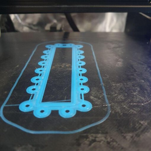
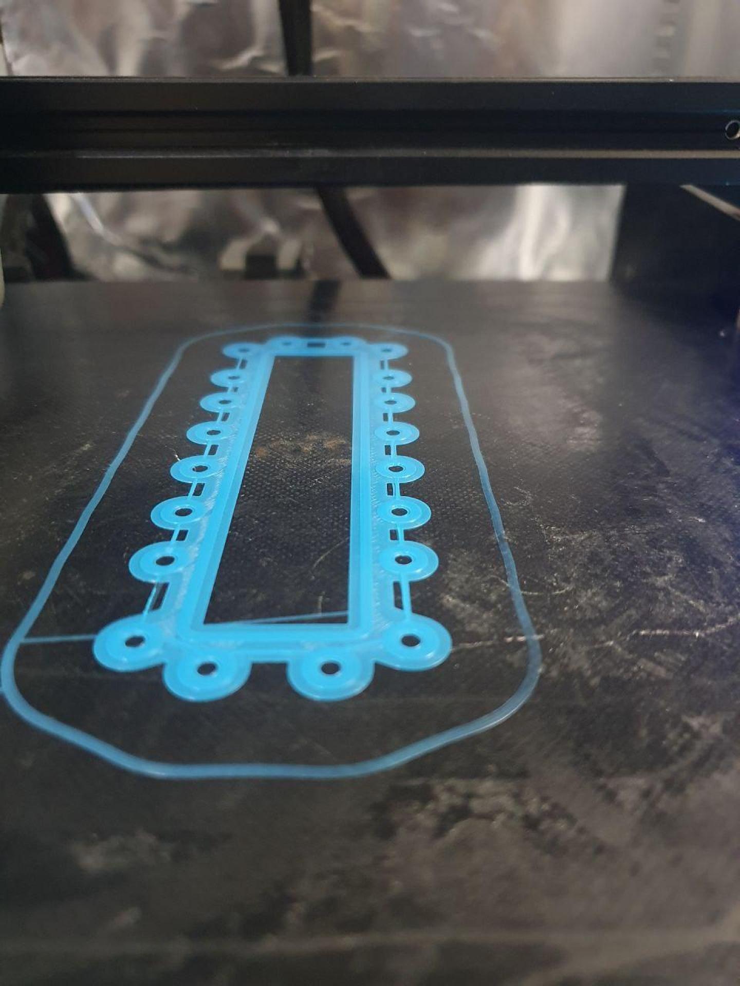
As you might have guessed, the flow fields are NOT 3D printed. They are machined from circuit boards using a CNC milling machine. As the epoxy / FR4 based material is very hard, there are certain requirements to be met for an effective milling process. Due to the abrasive nature of the material, special hardened cutters must be used. We have had good experience with diamond coated, diamond serrated cutters (Website). Although these special cutters are used, this material can only be milled if low horizontal and vertical feed rates are used. The following tools and settings were used to mill the flow fields:
Milling - First!
Small tip: Before you let your milling machine do it’s job. We recommend to do a dry run by telling the milling cutter tool to do the job just 20 mm above the actual circuit board and above every other obstacle. If you can estimate that the tool is going the right path you can start the job.
Equipment:
- Sorotec VHM-diamond milling cutter (diameter in mm [article number])::
- 0.8 [LBDV.0080]
- 1.6 [LBDV.0160]
- Website
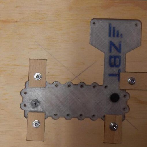
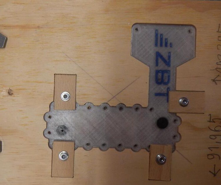
Milling of the flow channel (anode) and air vents (cathode)
- cutter: 0,8 mm diamond coated, diamond-toothed
- rotation speed: 20000/min
- horizontal feed rate: 1,5 mm/ s
- vertical delivery: < 1,6 mm
Cutting of flow field out of plates
- cutter: 1,6 mm diamond coated, diamond-toothed
- rotation speed: 20000/min
- horizontal feed rate: 4 mm/ s
- vertical delivery: < 1,6 mm
Drilling of 3,2 mm holes
- Drill: full hard metal
- spindle speed: 20000 /min
- vertical feed rate: 1 mm/s
Electroplating - Second!
Equipment
Coming soon!
