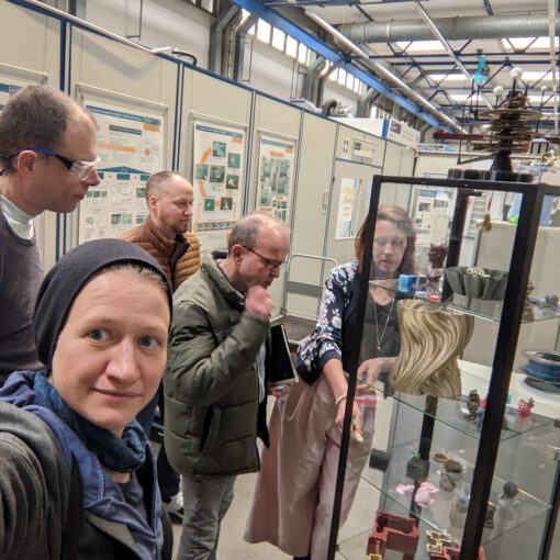
This time we meet in the hall of the chair for energy technology. Roland is reminiscing. He did his diploma thesis in this hall 22 years ago and has hardly been here since. Opposite the laboratory work surface where he had built fuel cells back then, he finds a board and remembers the countersunk screws that were already there back then and on which he had hung his sealings.
This is the first real meeting of the open fuel cell project team since we made the plan to completely rebuild Burghard’s cell while documenting and sharing this process from beginning to end. Burghard and Alexandra brought all components for one cell with them.
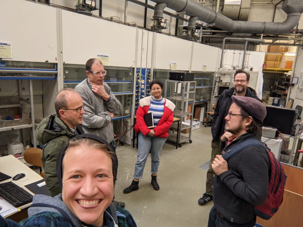
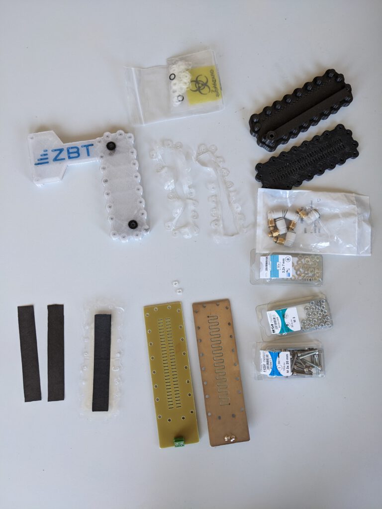
For today’s meeting, we have decided to assemble a first open fuel cell. We all huddle together in the office where the institute’s 3D printers are currently located. Alexandra immediately starts assembling the cell. Roland is happy and Henning takes pictures of every step. Here and there, Alexandra has to rework a few 3D printed parts – piercing some holes.
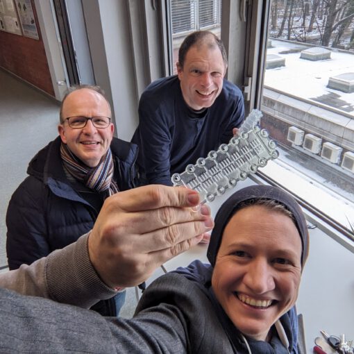
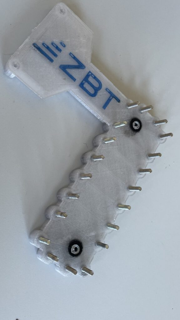
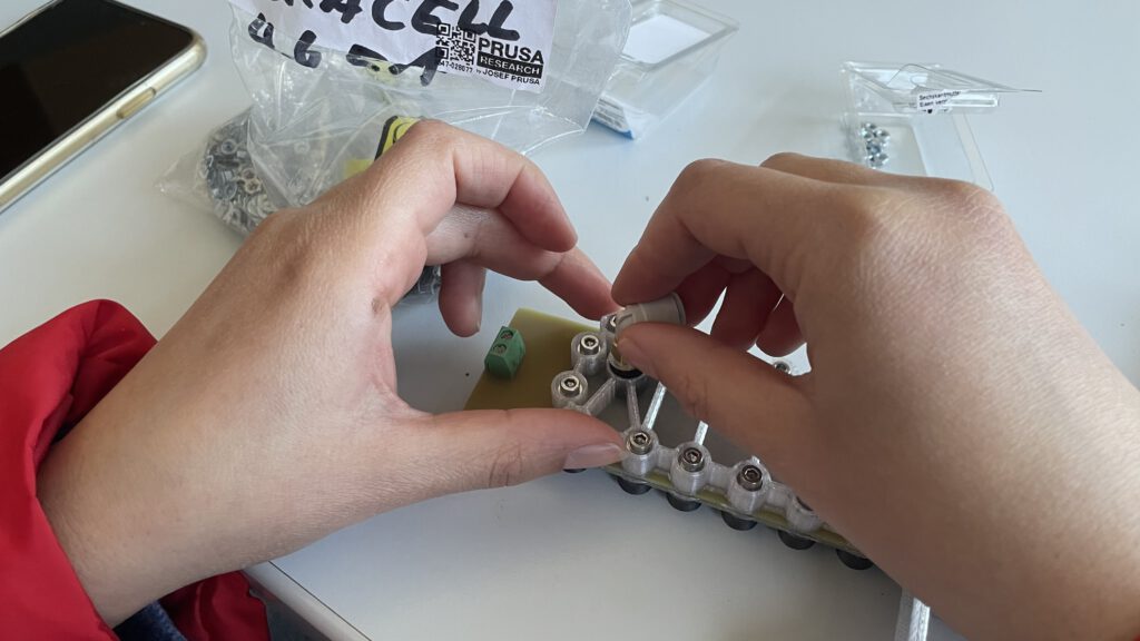
Then it really starts: the first step is to insert the screws with washers all around into the anode pressure plate – that’s the white 3D-printed part with the ZBT logo on it.
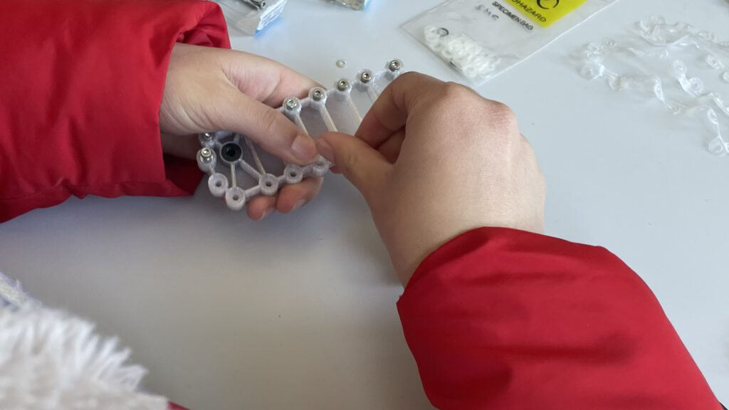
Then she puts in the two tiny flat gaskets for the hydrogen supply.
On top of that comes the flowfield which has been milled out of a PCB plate and gold-plated. And on top of that, the wobbly 3D printed thing: the flat gasket to seal the gas chambers in the anode compartment.
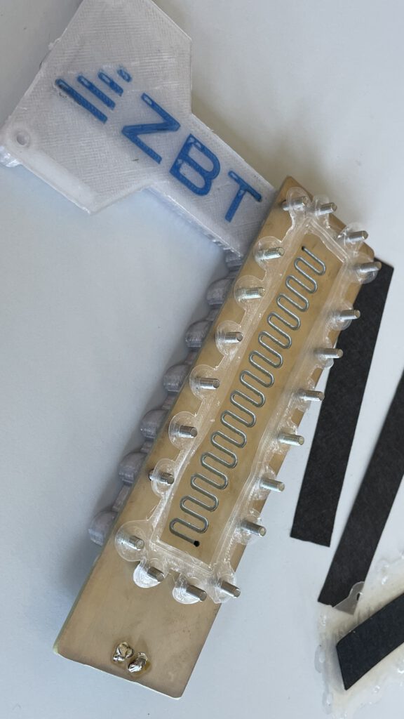
Now comes the actual magic layer with the ionomer membrane. So we need to explain a bit, how this whole unit, the memberane exchange assembly (MEA) is built: In order to position the compoenents, Burghard has built a small wooden scaffold on which corresponding columns sit exactly in all those places at which the screws are holding everything together at the end. Burghard used his CNC router and a drag knife to cut out the shape with the recesses for the screws on the outside and a rectangular recess for the membrane on the inside from commercially available laminating foil.
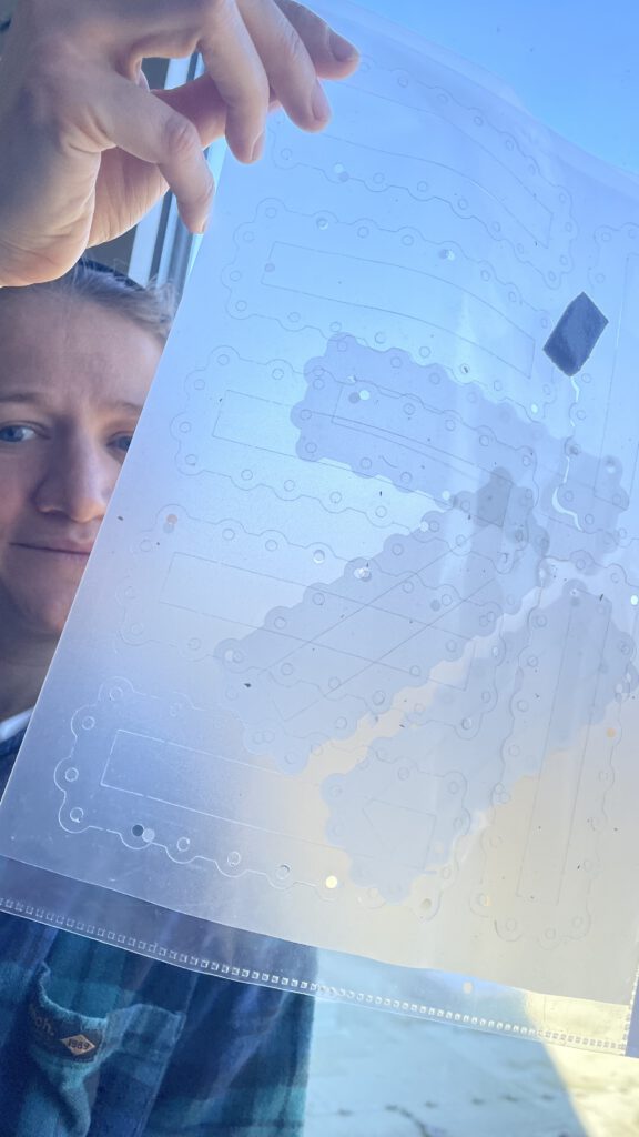
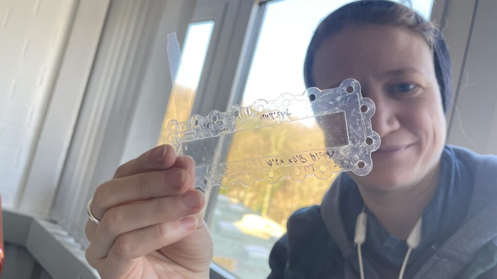
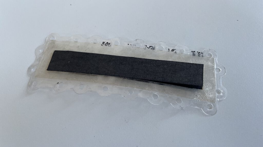
Then he carefully ironed together a layer of laminating film with the adhesive side facing up, a layer of pre-cut ionomer membrane, and a layer of laminating film with the adhesive side facing down all the way around. Roland had then pressed appropriately cut catalyst layers onto the top and bottom of the cut-out area, where the ionomer membrane lies exposed.
with the reinforcement and support made of laminating foil. We discuss
briefly: we will probably also make this available to people who want to
rebuild the Open Fuel Cell, since the membrane and catalyst layers are
commercially available only in larger quantities and the assembly of the
MEA is quite a fiddly job.
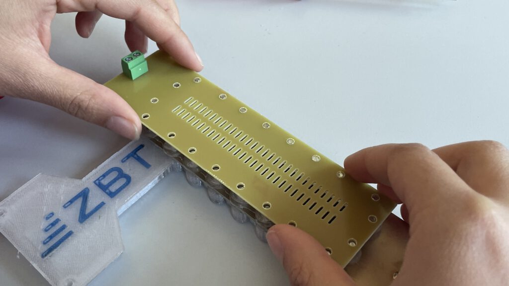
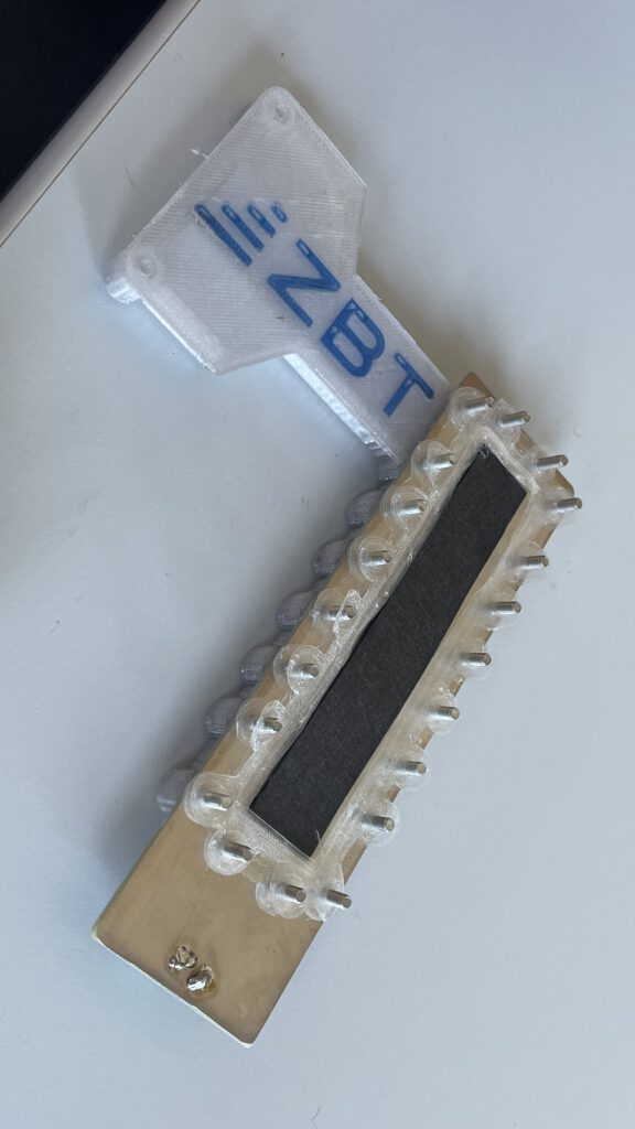
All that’s now left to do is to place the second pressure plate on top and insert the nuts there.
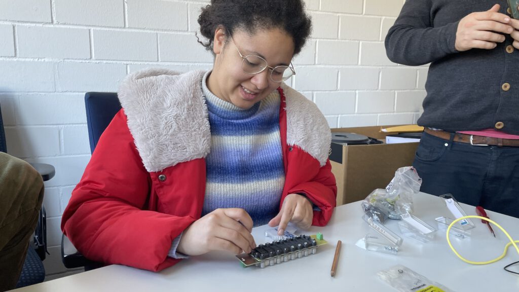
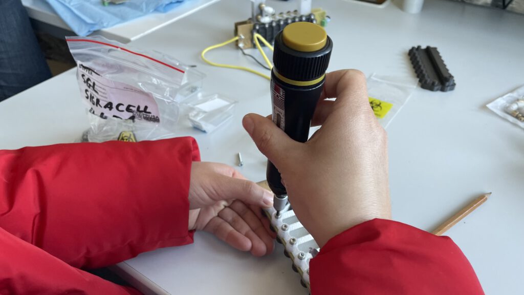
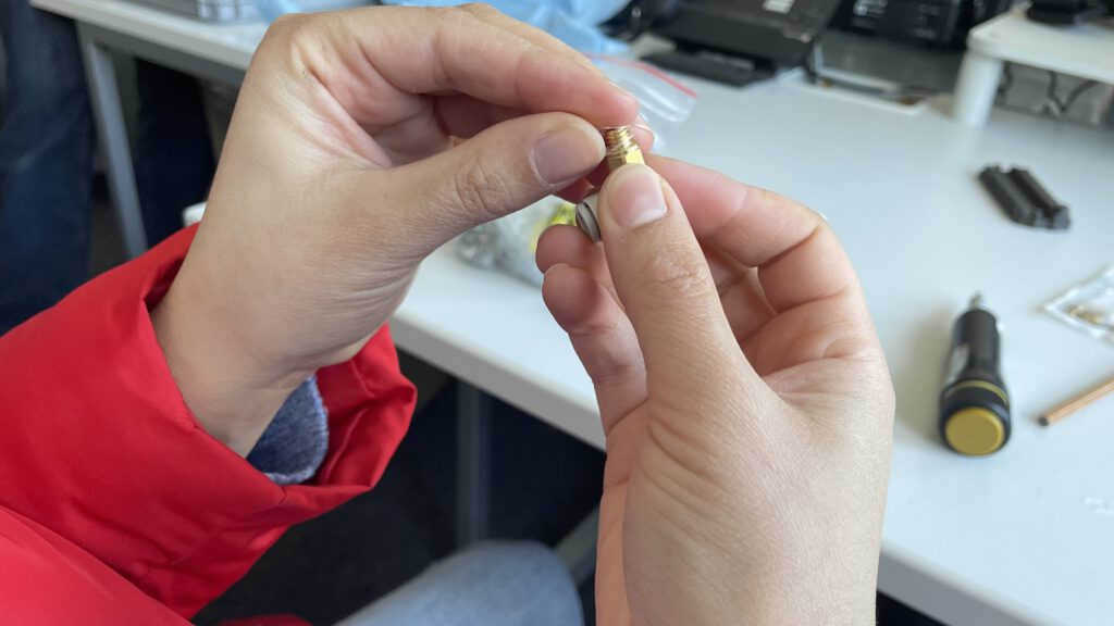
So, now Alexandra only still need to insert the tube connectors on the anode side. Burghard had milled a thread in the intended places (where the black filament is), Alexandra now screws in the SMC connectors. But before she does that, she puts two thin gaskets on each of them.
And with that, the cell is fully assembled – the exciting moment would now come when we check the cell for leaks. For today, however, we’ll leave it at the assembly stage.
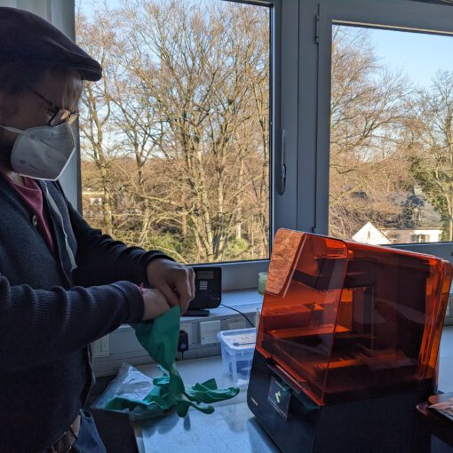
Actually, we still wanted to start 3D printing one of the pressure plates on the SLA printer that Leander purchased for the chair of energy technology today. Burghard had printed the plates of his cells with a filament printer and the plan is to rebuild all components on other instruments during our meetings. However, Leander and Burghard discover that something went wrong with the export of the files. Burghard wants to send Leander new files by tomorrow so that Leander can start 3D printing tomorrow. 🙂
