The core idea behind the Open Fuel Cell is to unleash your creativity when it comes to modifying individual components—or even redesigning them entirely to match specific experimental requirements. So why not replace the “original” flow fields, which are fabricated from electronic circuit boards by milling, with flow fields made completely of sheet metal using a deep-drawing process? Sheet-metal flow fields represent a “state-of-the-art” approach in many commercially available fuel cell systems.
When you think of metal, you also think of corrosion—and rightly so. That is exactly why so much emphasis is placed on protecting the original circuit-board flow-field plates with a thick gold layer (see the blog entry “The Great Corrosion”). To gain a deeper understanding of corrosion processes inside an operating fuel cell, Fachhochschule Südwestfalen and ZBT initiated the research project “CORROMAP.” One idea for obtaining detailed insights sounds simple at first glance: place many reference electrodes inside the MEA and the metallic flow fields, then operate the instrumented cell under all possible—and impossible—conditions.
This is where the challenges begin.
Accommodating all those experimental electrodes inside a PEMFC requires a lot of space and extensive modification of the cell design, especially if commercially available cells are used as the starting point. The second challenge is the test equipment needed to operate “fully fledged” commercial cells. Unless you work in a company or laboratory specialized in fuel cell technology, this (expensive) equipment is often simply not available.
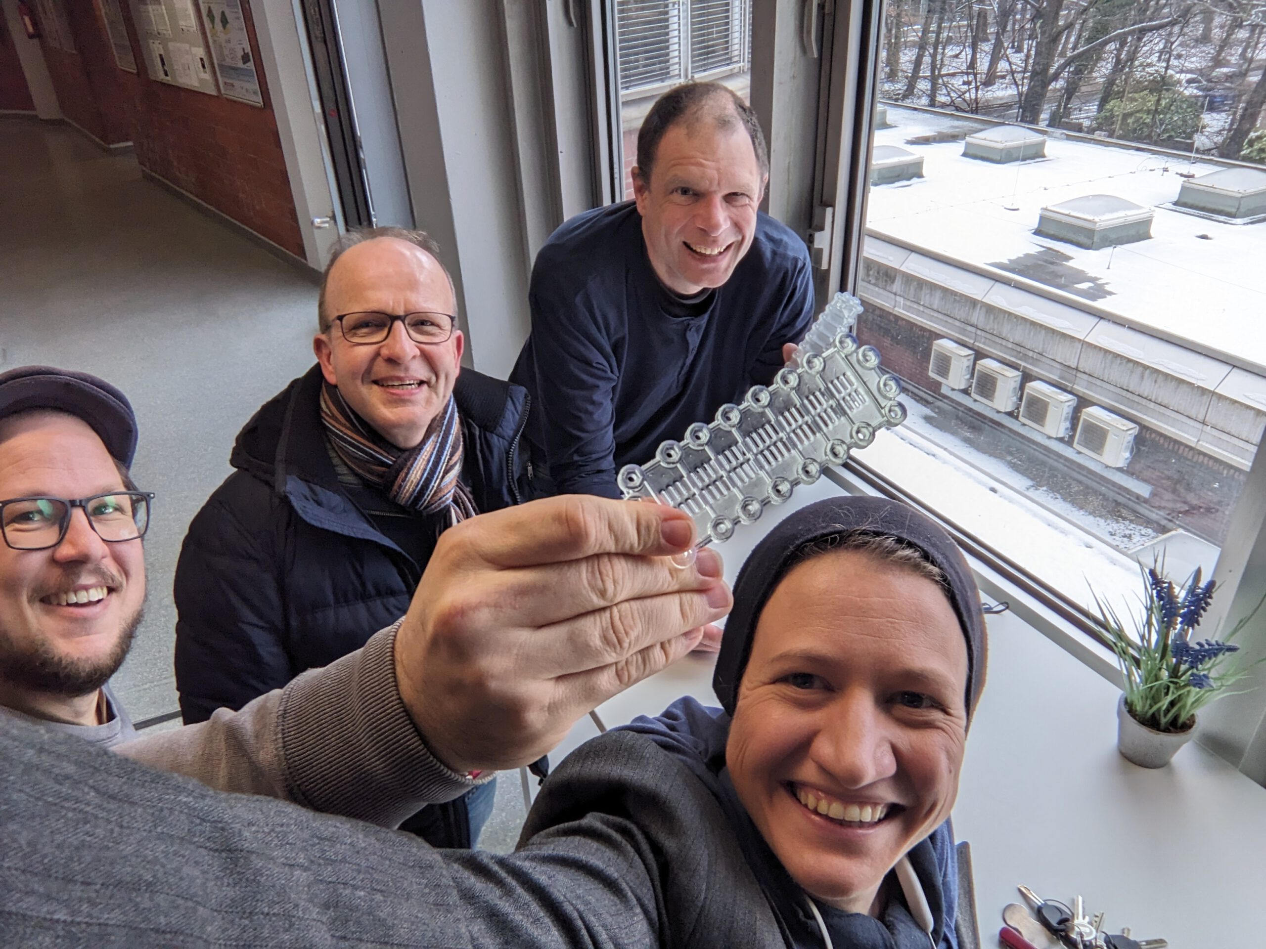
Since the Open Fuel Cell was designed for easy modification and operation with a minimal experimental setup, it was a natural choice to adapt the OFC and turn it into a workhorse for upcoming research projects. And adapt it we did—just look at the pictures (figure: Design of the full metal OFC, The full metal OFC).
Key design changes
1) Deep-drawn metal flow fields
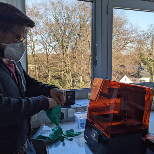
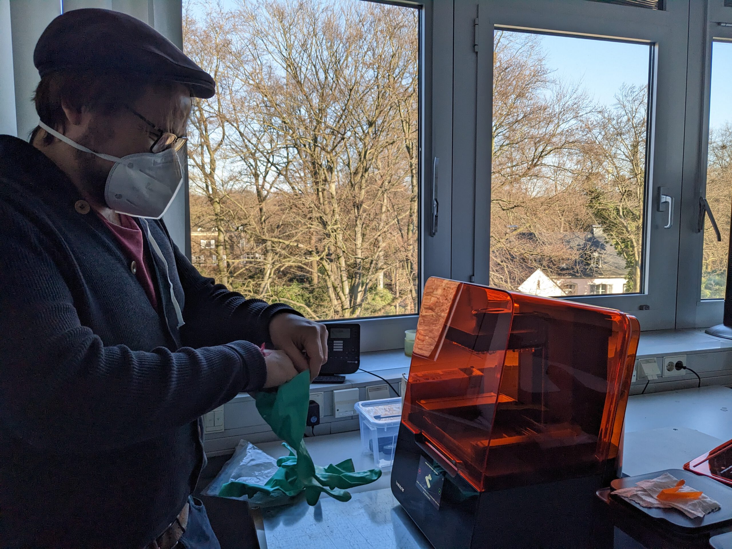
The most obvious change is the flow fields themselves. They are made from 0.1 mm sheet metal using a mould for deep drawing. In keeping with the spirit of the OpenFuelCell project, the mould is simply fabricated via 3D printing. Compression of the mould is done using clamps borrowed from a wood workshop—ideally after a good breakfast (figure: 3D-printed deep-draw mould). Despite the simple tooling and procedure, the plates can be formed with reasonable quality.
2) An interface adaptor between flow fields and end plates
Another modification was required in the interface between the flow field and the end plates. With the original circuit-board flow fields, this interface is straightforward: the plates have a flat, robust surface that provides even contact to the end plates. That is not the case with deep-drawn metallic plates. These three-dimensionally structured plates offer only limited contact area to the end plates, and their structure can be flattened if excessive force is applied. Therefore, adaptor plates made from an elastomer had to be developed and integrated into the modified OpenFuelCell. This part is also 3D-printed—of course.
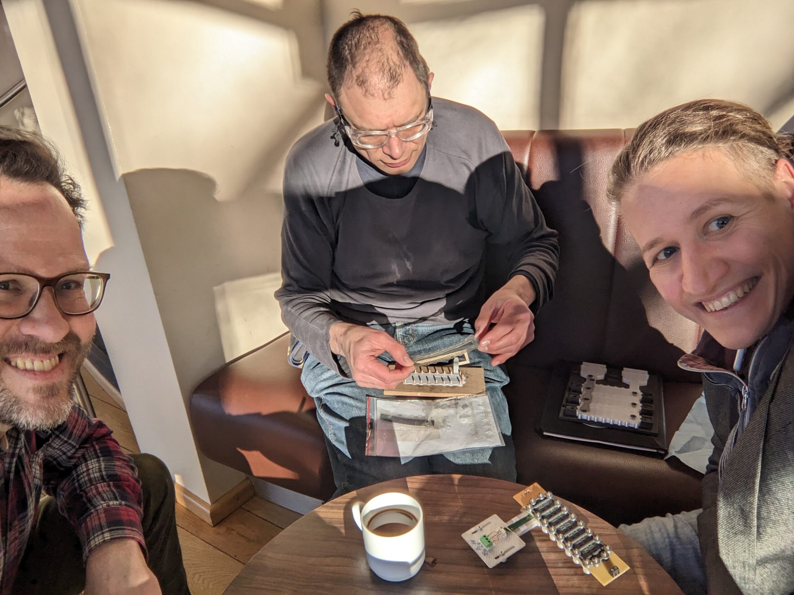
3) Updated current collection
A further modification was needed for the current collector. The original clamps soldered onto the flow-field plates cannot be mounted to stainless-steel plates because soldering simply does not work in this case. In addition, the electrical conductivity of the base material matters: the in-plane conductivity of a 35 µm copper layer on a circuit board is significantly higher than that of a 100 µm stainless-steel sheet. To keep ohmic losses as low as possible, the current collectors are clamped onto the sides of the metal flow fields.
4) Closed cathode with controlled airflow
With the full metal design, the previously open cathode is no longer truly “open” or directly exposed to ambient air. This means the air must be pumped through the cathode flow field using a compressor. The airflow delivered by the compressor can be varied by applying different voltages. Apart from this additional compressor, the overall experimental setup remains quite simple and can therefore be used almost anywhere.
Does it work?
Yes—it certainly does. See below the performance diagram of the full metal OFC applying different airflow rates to the cathode by varying the compressor voltage.
The main characteristic regions of the polarization curve—activation overpotential, ohmic overpotential, and diffusion overpotential—can clearly be identified. The closed-cathode design combined with an external compressor also means the airflow through the cathode flow field is reproducible and can be precisely controlled by adjusting the voltage applied to the compressor.
Conclusion
Within a certain range, your imagination is the only real limit when it comes to designing your own fuel cell experiments.

